Rack and pinion making strange noises
- Check drive tension screw is set fully and bottomed out
- Check pivot screw is tightened fully
- Ensure the pinion is greased properly
Machine moving roughly / making sounds over Y-axis joint on the table
- Go back to assembly instructions to ensure proper procedure in aligning rack and linear rail using tools and jigs
- Check that the left and right Y-axis sections are not mixed up, this will cause issues with the matched pair
Machine is not moving at all
This could be attributed to motor-related firmware settings and/or electrical connections.
1. Is the motor getting power? Check that a small green LED is illuminated near the two pin power connector on the back of the motor. Also try turning the motor – you should not be able to.
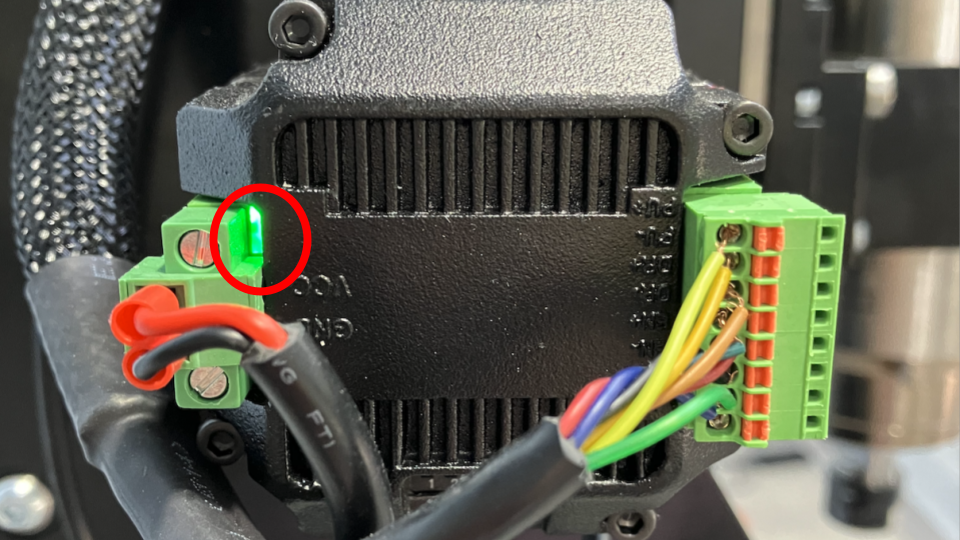
2. If you see an occasional red light on the motor, and you are able to spin the motor shaft by hand, then the machine is in an alarm state. Power cycle the machine to reset this.
3. On gSender, in Config, under Motors, check that the following settings match:
Step idle delay = 255
Step pulse invert = no toggles on
Invert stepper enable pin(s) = no toggles on
Ganged axes direction invert = Y-axis toggle on
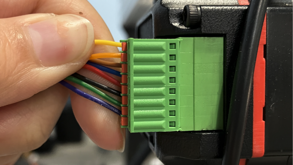
4. Check that the 8 pin connector going to the motor has all of its connections intact and are not loose. To insert wire into each terminal use a small flat screwdriver to press down on the orange tab to open the terminal. Tug wires to check they are secured.
Incorrect motor behaviour (direction, speed, distance)
This could be related to firmware settings, electrical or mechanical setup.
1. On gSender, in Config, at the bottom of the page select the AltMill 4x8 profile in the dropdown. Then at the left side, go to Motors and make sure the settings are at their default. If they are not default, you will see the setting highlighted in YELLOW. You can restore the individual setting using the "cycle" icon. See example below.
2. Check that the DIP switches on each motor are in the proper positions, as shown in the photos below. Please note that X and Y motors will be set differently from Z.
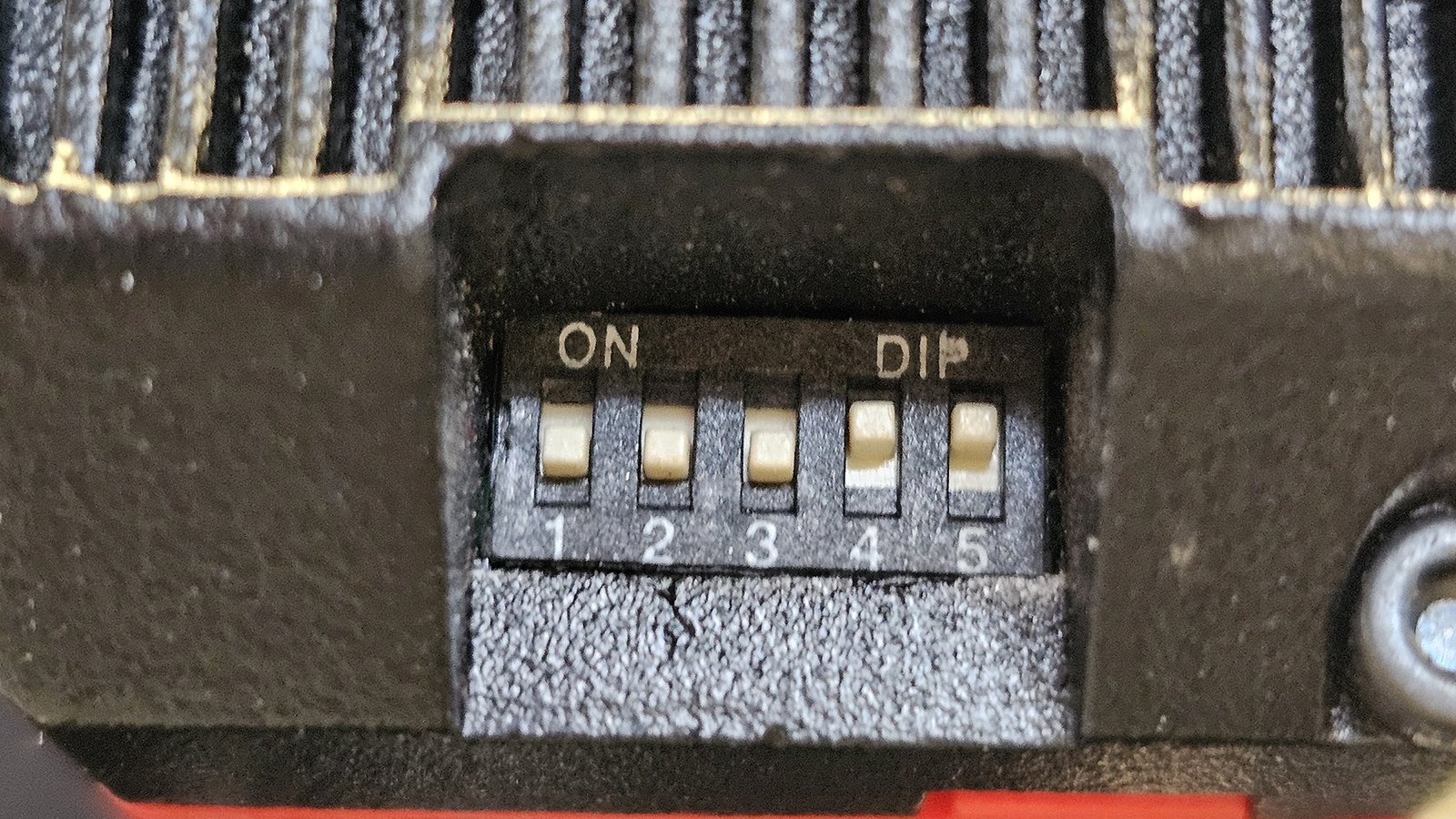
Correct motor DIP switches setting for X and Y-axis, from 1-5: OFF OFF OFF ON ON
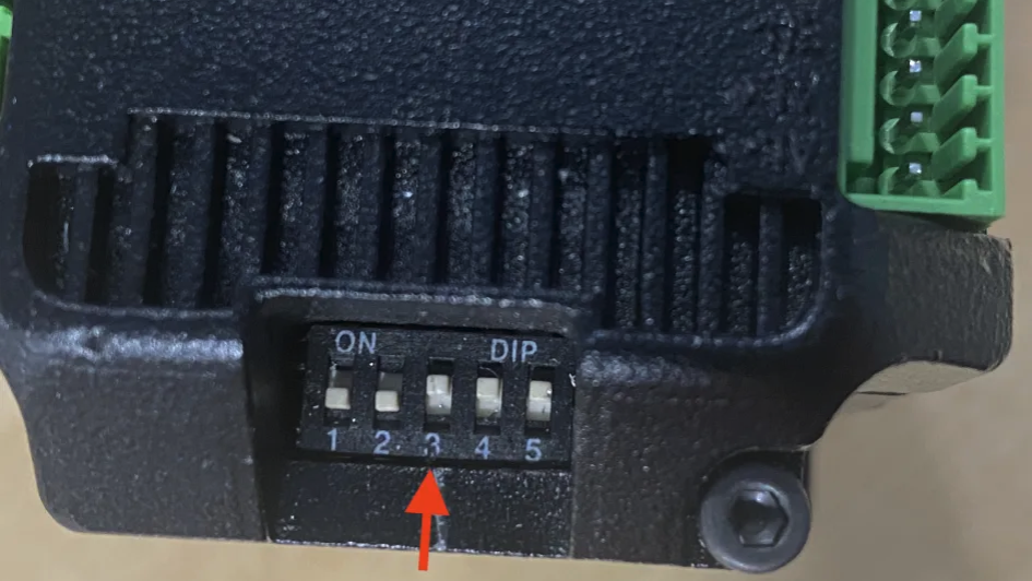
Correct motor DIP switches setting for Z-axis, from 1-5: OFF OFF ON ON ON
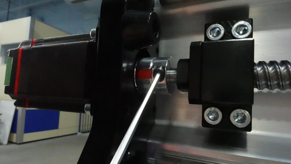
3. Make sure that the couplers are tightly fastened onto the ball screws and motor shafts.
Spindle not spinning up as expected
See the following related articles:
Alarm 14 / Spindle not responding
This usually is due to communication issues between the VFD, spindle and controller. Please see this article: Alarm 14 Troubleshooting
Alarm 2 ‘Machine travel exceeded’ during a job
This soft limit error occurs when you are trying to run a job that exceeds the machine’s bounds.
1. First, you can try changing the position of your project’s origin/zero on your CAM software, then save the new g-code file.
2. Next, run the homing sequence on your machine using gSender, so that the machine knows what its limits are.
3. Then, jog your machine and set your zero so that the entire project fits on your machine work area. Load up the g-code file and start the job.
4. If the above does not work, you can go into Config on gSender and under Homing/Limits, disable soft limits ($20) temporarily. Turn OFF/ON the controller to have the change take effect.
Alarm 10 or Alarm 15 when homing
- Identify whether the alarm triggers immediately, or if it triggers at a specific axis while homing.
- All Axes: Ensure flags and bump stops are installed correctly according to the assembly instructions.
- Y-axis: Make sure the limit switches for the Y-axes are not swapped, check that the Y1 motor cable is connected to the Y1 limit switch and motor ports on the controller, and similarly for the Y2 motor cable. Also check that the sensors are adjusted properly, set them until they bottom out.
- Z-axis: Adjust using this guide: AltMill - X and Z Limit Switch Adjustment.
Alarm 10 when motor alarms are also triggered
Check for the motor alarm on the Console in gSender, as well as the SLB-EXT controller lights, the light indicates which motor is affected.
This means that the closed loop stepper motors are experiencing mechanical resistance, or the closed loop circuit is interrupted which may indicate a faulty motor. Turn OFF/ON the controller, move the machine away from any limit switches, bump stops, to see if the alarm clears. If not, use the Motor Troubleshooting Chart attached in the bottom of this article.
Error 33
Export your toolpath using the grbl mm post-processor, instead of the inch post-processor. Exporting toolpaths in inches can cause this error due to how the CAM software rounds numbers, so there is a higher chance there will be two lines with identical data in the g-code (which the controller does not like).
Zeroing my axes does not work
Please go to this troubleshooting article: Pressing Zero for Axes not working
Machine homes or jogs in the wrong direction
Please go to this troubleshooting article: Machine cannot home, moving away from sensors