This troubleshooting guide is for both the AltMill and LongMill using either the SLB or the SLB-EXT.
Alarm 14 will appear on earlier firmware software. If you have updated your firmware, have an Altmill 4x8, or have an SLB Lite, or SLB-EXT V2.0, it will be an alarm 19
Symptom(s):
- An Alarm 14 / Alarm 19 appears and won't clear
- An Alarm 14 / Alarm 19 happens when starting a job
- An Alarm 14 / Alarm 19 appears at startup
- r00.0 on VFD
This would point to an error in how you’ve physically set up your spindle, how you’ve configured the SLB EEPROM values, or how you’ve configured the PD values on your VFD.
Troubleshooting Lights
Confirm that both communication LEDs are flashing when the VFD is connected. Connect to the control board through gSender or other sending software. If only one or none of the LEDs are flashing, there is a communication issue either with the control board, the VFD, or the RS485 cable. (#4 and #5 on the diagram).
If one of the LEDs is flashing, but the other is either off or stays on. Check the following resolutions. If none of the resolutions solve the problem, the issue could be with the communication chip with the control board. You must be connected to the control board with sofware for the communication LEDs to light up.
Resolution(s):
- Startup procedure
- Restore default configuration
- RS485 wiring
- Troubleshoot RS485 Cable
- Troubleshoot Spindle Cable and Spindle
- Test VFD Operation
- Verify VFD Settings
- MODVFD setup
Startup Procedure
Alarm 14 during startup (or the spindle not spinning) comes on usually when you don’t turn on the controller and spindle in the correct order. The controller and VFD need to “handshake,” and if the conditions aren’t met, even if they’re on at the same time, they won’t go through with the handshake.
Assuming the controller is plugged into power but turned OFF:
1. Plug the spindle into power, and the VFD should flash with red text
2. Then turn on the controller using the power toggle
This is the correct way to turn on your controller each time, to avoid Alarm 14.
Restore Default Configuration
- Download the setup file AltMill_Sienci_Spindle_Configuration__SLB-EXT or LongMill Spindle Configuration (SLB Controller only)
- Open gSender and run the attached setup code. This will set all EEPROM settings to what they should be
- Power cycle everything. Turn off the VFD and the controller. Close gSender
- Turn on the VFD first, then the controller, then connect to gSender.
- Ensure the VFD is plugged into the back of the controller above the power switch.
- Go to the console, type $spindles and check if H100 is selected as “Current spindle”.
- In Console, type M3S10000 to see if the spindle spins properly.
-
In Console, type M5 to see if the spindle stops.
RS485 Wiring
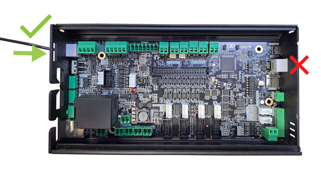
First, please ensure you have plugged in the RS485 cable in the correct port on the SLB. The RS485 cable should be plugged into the connector above the OFF-ON switch and NOT the connector below the USB cable.
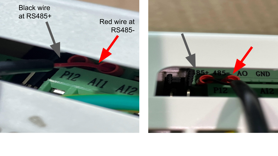
Ensure that the RS485 cable is wired correctly at the VFD side and plugged into the telephone jack on the SLB-EXT. The red wire goes to RS485-, and the black goes to RS485+. If you need to modify this, make sure to unplug the VFD from power first.
Troubleshoot the RS485 Cable
To test if the cable is the issue, please do the following:
Remove the green 4-pin connector from the control board, located beside the RS485 jack. Using 2-strand wire, install the wires as shown. In my example, the red wire is connected to the 485+ on the VFD and to the A pin on the green connector. Black is wired into the RS485- on the VFD and the B pin on the green connector. This setup is the reverse of the RS485 connection


Then run the default configuration setup above.
AltMill_Sienci_Spindle_Configuration__SLB-EXT or LongMill Spindle Configuration (SLB Controller only)
If the spindle moves, the cable isn't the issue and won't need to be replaced. If the spindle doesn't start, the issue could be on the VFD or the control board. Confirm the correct parameters are set on the VFD by following the instructions below. If the settings are correct, reach out to customer support for next steps.
Test VFD for Operation
Put the VFD in manual mode and run from the control panel. If the VFD starts up and runs in manual mode, move to the next step and confirm VFD settings
Incorrect VFD Settings
Ensure all settings on the VFD match the following below: download the attached PDF for a printable copy
To change settings, follow the example below. The VFD must be unlocked before changing any parameters. Unlocking the VFD
| Function Code | Default Value | Parameter Name |
| F000 | 0 | Parameter Locking (Value 1 is unlocked) |
| F001 | 2 (0) | Control Mode Automatic ( Value 0=manual) |
| F002 | 2 (3) | Frequency Selection Automatic (Value 3= manual) |
| F003 | 400 | Main Frequency |
| F004 | 400 | Reference Frequency |
| F005 | 400 | Maximum Operating Frequency |
| F006 | 10 | Intermediate Frequency |
| F007 | 0.5 | Starting Frequency |
| F008 | 380 | Maximum Voltage |
| F009 | 14 | Intermediate Voltage |
| F010 | 5 | Low-Frequency Torque boost Voltage |
| F011 | 125 | Lower Frequency Limit |
| F014 | 10 | Acceleration Time 1 |
| F015 | 10 | Acceleration Time 2 |
| F016 | 5 | |
| F118 | 1 | Over-Voltage Stall Protection |
| F119 | 155 | Stall Level During Acceleration |
| F120 | 150 | Stall Level During Constant Speed |
| F121 | 5 | Deceleration Time for Stall Prevention |
| F122 | 370 | Prevent of Over-Voltage Stalling Level |
| F123 | 1 | Over-Torque Detection Mode |
| F124 | 0 | Over-Torque Detection Level |
| F125 | 1 | Over-Torque Detection Time |
| F126 | 0 | Counter Memory After Power Failure |
| F128 | 1 | Cooling Fan Control |
| F129 | 360 | Dynamic Braking Voltage |
| F140 | 1.5 (2.2) | Rated Power of Motor Kw, 1.5kw (2.2kw) |
| F141 | 110 (220) | Rated Voltage of Motor, 110 Volts (220 volts) |
| F142 | 7 (11) | Rated Current of motor |
| F143 | 2 | Number of Poles |
| F145 | 2 | Automatic Torque Compensation |
| F146 | 40 | Motor No-load Current |
| F147 | 0 | Motor Slip Compensation |
| F148 | 4 | Motor Slip Compensation Maximum Frequency |
| F149 | 100 | Motor Slip Compensation Filtering time |
| F150 | 2 | AVR Function (Automatic Voltage Regulation) |
| F151 | 0 | Automatic Energy Saving Function |
| F152 | 1 | Fault Restart Time |
| F154 | 0.5 | Allowable Outage Duration |
| F155 | 0 | Times of Fault Restart |
| F163 | 2 | Communication Address |
| F164 | 2 | |
| F165 | 3 | Communication Mode |
| F190 | 0 | Magnetic Flux Braking Enabled |
| F191 | 115 | Magnetic Flux braking Strength |
| F192 | 30 | Motor Oscilliation Compensation Factor |
| F193 | 0 | Output Open-Phase Protection |
| F194 | 0 | 0 Hz Inverter Input |
| F195 | 1 | VF Separation Voltage Control |
| F196 | 300 | Acceleration and Deceleration time of VF separation Voltage |
| F197 | 0 | Motor Reverson Operation |
| F198 | 0 | LSD Compensation Enable |
| F199 | 0 | Keyboard Up.Down Memory Function Selection |
MODVFD Setup
If the above does not solve the issue, a workaround would be to use MODVFD as the default spindle. This should work for spindles that communicate using RS485, such as the Sienci Labs Spindle (H-100), Huanyang, Durapulse, and Yalang. See instructions here.