An Alarm 10 can occur if there is an issue with the E-stop, sensors, closed-loop stepper motors, or cables. If you have incorrectly installed your limit switches, this will cause an alarm 10. This guide will troubleshoot the motor issues. You can find the E-stop troubleshooting guide here.
Issue(s):
- Alarm 10 during startup
- Alarm 10 during homing or moving the machine
- Triggered closed-loop stepper motor
- Motor alarm shown in console
- Stall light on SLB/SLB-EXT
- LED on back of motor is flashing red
- An axis is locking up mechanically
Triggered closed-loop stepper motor
This means that the closed-loop stepper motors are experiencing mechanical resistance, as if the machine bumped into something.
You can verify if the motor is an issue by looking at the following:
Console section in gSender. Above the alarm, there will be a message that will display what motor has been tripped.
The controller’s lights as outlined in the graphic below. Yellow LEDs indicate which motors are affected. If the motor is affected, you should be able to rotate the motor shaft with your hands.
To clear the alarm, you can power cycle the controller.
Bottom right corner of the SLB-EXT
Look at the back of the motors. A motor that has stopped and has triggered the Alarm 10, will have a flashing red LED. There is a brief pause between each section of flashing.
Resolution:
- Adjust Limit Switches
- Limit Switches Incorrectly Installed
- Test blue relay light
- Troubleshoot Mechanical Components
- Troubleshoot Electrical Components
Adjust Limit Switches
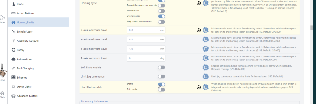
Disable hard limits in gSender. Otherwise you will get an Alarm 1 every time the sensor is triggered and it’s annoying when adjusting them. It’s found under Config, Homing/Limits, then Hard Limits enabled. After you press Apply Settings, remember to turn OFF and ON your controller to have the changes take affect.
For the Z axis
- Raise the spindle to the top.
- Loosen the back sensor nut and move the limit switch towards the spindle
- When the red light on the back turns on, loosen the back nut 1/4 turn more
- Lower the spindle
- Tighten the front sensor nut.
Adjustment shown in video:
For the X Axis
- Move the spindle to the left.
- Stop till there is a 1/16-1/8″ gap between the bump stop and the spindle mount
- Loosen the outside sensor nut and move the limit switch towards the spindle
- When the red light on the back turns on, loosen the back nut 1/4 turn more
- Tighten the inside sensor nut.
- Once complete, enable your hard limits.
For all axes, if you are using integrated bump stops, make sure to screw in the inductive sensor fully.
Limit Switches Incorrectly Installed
There was an update between the MK1 and MK2 Altmills for Limit Switch installation. MK1 Altmills used a rubber bump stop. The MK2 Altmill use a knurled integrated bump stop. The limit switch is installed inside this bump stop without a space between the bump stop and the sensor.
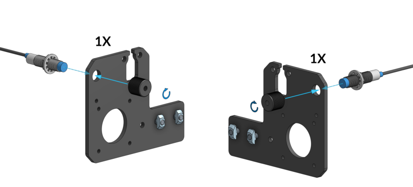
Ensure you have installed the Limit switches correctly for the X and Y axis
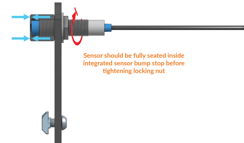
Install two (2) integrated sensor bump stops at the ends of the inductive sensors to secure them onto the back end plates. Thread the bump stops over the end of the sensor until it bottoms out, only hand-tightening these until snug. It is important that this bump stop is fully seated on the ends.
Then, tighten the rear sensor nut with a lock washer on the back of the sensor, to clamp it on the end plate.
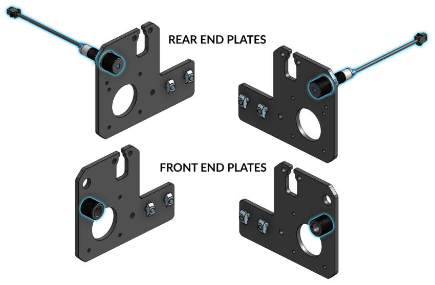
Once assembled, your end plates should look like the following image:
Test Blue Relay Light
If the blue light near the relay on the SLB-EXT is OFF throughout the startup process (after E-stop press and release), there could be a short circuit caused by one of the motors. If that is true, please try the following steps:
1. Unplug all the motors from the controller, and then see if the blue light comes on when you restart the controller.
2. Unplug all motors. This time, test 1 motor at a time to see if the blue light comes on after a restart. If the blue light is OFF, then we know that is the faulty motor.
Troubleshoot Mechanical Components
A motor or it's components might not be moving correctly, are binding and preventing the motor from moving as expected. Please check the following
Motor coupler
- Ensure both halves of the motor coupler are tight against the red bushing. If the coupler has separated, the motor or the ball screw isn't moving correctly. It can take some force to tighten the screws on the motor coupler
- Make sure the screws are tight and not slipping on the motor shaft or the ball screw
- Ensure the motor coupler is positioned equally on the motor shaft and ball screw
Bad/Locked Motor
- Turn off the controller to deenergize the motors.
- Rotate the ball screw by hand. It should move freely without any resistance.
- If there is resistance or it won't move. Undo the motor coupler from the ball screw side.
- Rotate the ball screw. If the ball screw moves freely and without resistance, the motor could be damaged.
- Rotate the motor coupler. If the motor won't rotate, a replacement will be necessary
- If the ball screw doesn't rotate freely the issue could be with the ball screw bearing, or linear guide bearings.
Linear Guide Bearing Test
- Undo and remove the 4 screws from the ball screw bearing. For this test, remove the screws from both Y-axis if needed.
- Slide the gantry back and forth. It should move freely without resistance. If there is resistance, or it won't move, the linear guide bearings will need to be replaced.
Ball Screw Bearing Test
- With the ball screw bearing free from the gantry, rotate the ball screw; it should move freely. If there is resistance, an application of grease can help - Altmill Maintenance
- If the ball screw bearing can't move, a replacement ball screw bearing assembly is necessary
Troubleshoot Electrical Components
Note that Alarm 10 could also be from motor cables incorrectly wired. If there is motor warning, have them look at the back of the motor.
- Flashing red LED, motor was tripped.
- No flashing LED, likely wrongly assembled cable. Check the wiring.
- Make sure they're wired the same as the other motor cables (however, if all 4 axes have motor alarm, most likely it is a motor harness issue on all axes)
Download and follow the Motor Components Troubleshooting chart to isolate the affected component.
#closed-loop stepper motors , #alarm 10,